The output of a microphone is an electrical signal source. As with any real signal source, it can be described as an imaginary combination of an ideal voltage source in series with an impedance. The ideal voltage source generates an output voltage that is completely independent of the connected load. Such a situation does not exist in the real world, since the ideal voltage source would supply infinite current in the event of a short circuit. The series impedance models the load-dependent reduction of output voltage that occurs in practice.
If a load is connected to the microphone, a voltage divider is formed from the output impedance of the microphone and the input impedance of the load. If you know both impedances, you can calculate how much the output signal will be reduced by the load connected to it. The actual reduction in voltage is thus an effect arising from the interaction of properties of both the source (output impedance) and the load (input impedance). A microphone manufacturer can provide only the output impedance for this calculation.
The mode of microphone connection is designed for voltage transfer. (In the early days of electroacoustics this was not the case, but today it is the norm.) This means that the output voltage drops as little as possible under load. This is achieved when the load impedance is considerably higher than the output impedance. Up to a point this even allows several loads in parallel to be connected to one output ("bridging" the output).
For balanced microphones, the load impedance should be 1 kΩ or higher. The output impedance of the microphone should be 250 Ω or less. These impedances are measured differentially, i.e. between the two signal conductors. Balanced connections also have a common mode impedance, which is measured between the combined signal conductors and ground. This should not be confused with the output impedance.
A low output impedance also helps to drive larger load capacitances such as those that occur with long cables. This prevents a frequency-dependent drop in level from occurring. In addition, low output impedances are less sensitive to interference. On the other hand, very low output impedances can increase the tendency to parasitic oscillations.
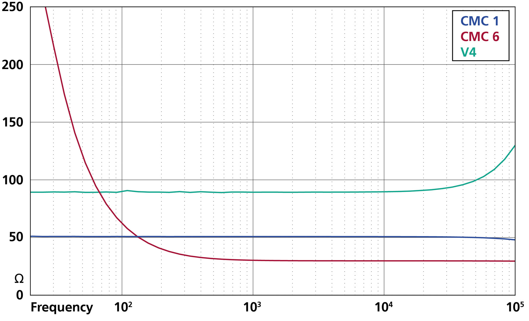
The term “impedance” indicates that as a rule, it is not simply an ohmic resistance, but a reactance whose behavior can vary with signal frequency. For a complete picture, therefore, output impedance or load impedance as a function of frequency would have to be plotted in a magnitude and phase diagram.


